RDTech RD series
 | |
| Status | supported |
|---|---|
| Source code | rdtech-dps |
| Channels | 1 |
| Voltage/current (CH1) | 0-60V / 0-6/12/18A |
| Connectivity | serial over USB/WiFi/TTL (3.3V) |
| Features | programmable presets, values, output, over-(voltage,current,power) thresholds. |
The HangZhou RuiDeng Technologies RDTech RD6000 series consists of a range of DC to DC buck regulator modules which communicate by means of Modbus over serial.
| Model | Voltage | Current | Max Power |
|---|---|---|---|
| RD6006 | 0-60V | 0-6A | 360W |
| RD6012 | 0-60V | 0-12A | 720W |
| RD6018 | 0-60V | 0-18A | 1080W |
See RDTech RD series/Info for USB connection details.
Hardware
These modules are not complete power supplies which are ready for use out of the box. Instead the buck regulator modules are supposed to get supplied from an external source. Optional kits are available, cheap bricks or batteries are another use scenario, as is supplying several regulator modules from one common supply. Due to the buck configuration the input must be at least 1V above the desired output voltage. Or put differently the maximum output voltage is 1V below the input voltage.
The regulator module provides serial over USB (micro USB on the front panel) as well as TTL serial (internal pin header) for Modbus over serial communication. WLAN to serial modules (ESP based) are available as an option for these internal pin headers.
WLAN access is currently not supported by the sigrok driver. Its operation is yet to get determined, it's yet to be seen whether this "feels" like a serial cable or can disguise as one. The mobile phone app is unusual in that the WLAN module(!) acts as an access point and the app connects to the entity which provided the station's properties. :-O The details of this network communication are yet to get determined before support can get implemented. Alternative firmware for the ESP module exists which happens to also run "the UI" on that module, which radically differs from the mere Modbus relay mode. When ESP firmware would become available which merely relays serial payload data while its network address is known then sigrok support would be transparent.
Hardware details (MCU section)
- MCU: STM32F103
- U13: 2Pai Semi π122U31 Dual channel digital isolator
- U12: Gainsil GS8332 Dual Op-Amp
- U11: Winchiphead CH340E USB to serial
- U8: Winbond W25Q32JV 32MBit (4MB) SPI Flash
- U6: Fujitsu MB85RC04V 4KBit (512B) FRAM
- U1: Titan Micro TM1650 LED Driver
- U5/U0: M5333B? 3.3V regulator?
- LCD: Z240IT010 2.4" 240x320 TFT panel (ILI9341, 18pin connector, 0.8mm spacing, SPI serial)
J2 Connector Pinout:
| VDD | 1- | O | -8 | |
| BOOT0 | 2- | -7 | ||
| GND | 3- | -6 | ||
| PA14 (SWCLK) | 4- | -5 | PA13 (SWDIO) |
WiFi Header Pinout::
| NC | 1- | O | -8 | VCC |
| 3.3V | 2- | -7 | RXD (PA10 / UART1 RXD) | |
| (PA6) EN | 3- | -6 | TXD (PA9 / UART1 TXD) | |
| GND | 4- | -5 | NC |
Photos
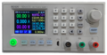
front
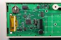
pcb, mcu part

Protocol
The protocol is similar to the RDTech DPS series, which is why a common sigrok driver handles either variant. The bitrate defaults to 115200, the register layout (addresses) and register value presentation (endianess) differ. But the interpretation of registers which have the same meaning among DPS and RD is identical, as is anything above the logical interpretation of register content.
(older notes below, TODO adjust or combine them with the above text)
Serial baudrate defaults to 115200/8n1 and Modbus slave address defaults to 1. Both can be changed in the main menu at any time. There is also an option using WiFi instead of USB/Serial, which uses a fixed Baudrate of 115200/8n1.
sigrok use
Scan for the device.
 $ sigrok-cli -d rdtech-rd:conn=/dev/ttyUSB0 --scan
 The following devices were found:
 rdtech-rd - RDTech RD6006 v1.28 [S/N: 12340] with 3 channels: V I P
List the device's properties.
 $ sigrok-cli -d rdtech-rd:conn=/dev/ttyUSB0 --show
 Driver functions:
     Power supply
 Scan options:
     conn
     serialcomm
     modbusaddr
 rdtech-rd - RDTech RD6006 v1.28 [S/N: 12340] with 3 channels: V I P
 Supported configuration options:
     continuous: on, off
     limit_samples: 0 (current)
     limit_time: 0 (current)
     voltage: 0.000000 (current)
     voltage_target: 0.000000, 60.000000, 0.010000
     current: 0.000000 (current)
     current_limit: 0.000000, 6.000000, 0.001000
     enabled: on, off (current)
     regulation: CV (current)
     ovp_active: on, off (current)
     ovp_threshold: 62.000000 (current)
     ocp_active: on, off (current)
     ocp_threshold: 6.200000 (current)
Get samples from the device.
 $ sigrok-cli -d rdtech-rd:conn=/dev/ttyUSB0 --samples 2
 FRAME-BEGIN
 V: 23.98 V DC
 I: 0 mA DC
 P: 0.00 W
 FRAME-END
 META enabled: 1
 FRAME-BEGIN
 V: 23.98 V DC
 I: 0 mA DC
 P: 0.00 W
 FRAME-END
Manual Operation
I-SET and V-SET followed by number input or cursor/encoder navigation allow adjustment of the currently selected "live" channel, or are used to configure the presets. The output can be turned on/off while the regulator remains powered.
SHIFT-1 to SHIFT-9 recall previously configured presets. These either immediately take effect, or optionally can get ACKed or NAKed by the user before taking effect (setup option). Presets can get adjusted from the setup menu, or stored by means of the MEM button.
SHIFT-0 enters the menu. It may be surprising but the rotary encoder's click "is the ESC button". The combination of arrow keys, ENTER and ESC allow navigation across the screens, as well as fields within a screen. A field's value is changed by the rotary encoder.
SHIFT-. locks or unlocks the front panel (while the power button remains accessible, which can be surprising).
The vendor provided bilingual manual quite nicely explains the operation, including live graphs and other topics not mentioned here.
Resources
- User Manual on banggood and vendor sites
- Video Review
- EEVblog forum thread
- RD6006 Python module
- PC control and logging
- Python script for updating firmware