Protocol decoder:pjon
 | |
| Name | PJON |
|---|---|
| Description | The PJON protocol |
| Status | supported |
| License | GPLv2+ |
| Source code | decoders/pjon |
| Input | pjon_link |
| Output | — |
The PJON protocol specification documents the layout of frames which can get transmitted by means of several link layers, among them PJDL. Communication peers have local addresses in the 1..254 range, and optionally can reside in busses with 32bit IDs (often written in dotted quad notation similar to IPv4). Many of the protocol's frame fields are optional to reduce the overhead during transmission, their presence is controlled by a header configuration field. Both the essential header of a frame as well as the complete frame content are checksummed, the CRC method gets picked by the transmitter (longer frames mandate wider checksums beyond a given threshold).
Decoder
The sigrok project supports the interpretation of PJON frames including their communication via the PJDL link layer. These screenshots demonstrate the decoder implementation's use at different zoom levels, to either get an idea of ongoing communication from the bird's view, or inspect minute details when trouble shooting a configuration.
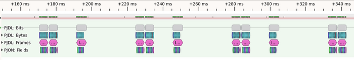
ping pong pairs, not ACKed frame, bus utilization
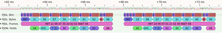
sync response is seen, turn in communication direction
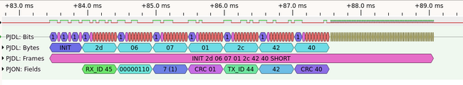
sync response is missing (times out)
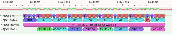
more details when zooming in
most details upon more zooming in


TODO Split the common PJON parts (upper layer) from the PJDL specific link layer parts. Two layers of protocol decoders will exist such that other link layer types can get added transparently. Perhaps link to the external spec if the text here would be a verbatim citation? Keeping a summary here may be helpful, keeping a copy might be less so (license should not be an issue, the spec was released to the Public Domain).
The PJON protocol v3.2 in local mode supports connectivity for up to 254 devices.
The packet format is dynamic therefore meta-data can be optionally included using the header as a bitmap of selected features. It supports interoperability between systems that use a different configuration and provides with high efficiency including only the protocol's features used and the overhead effectively required (5-22 bytes). PJON can be used for simple low-data-rate applications as an alternative to 1-Wire, i2c or CAN but can also be applied in place of IP to interconnect more complex networks.

The graph below shows the conceptual model that characterizes and standardizes the communication. Its goal is the interoperability of diverse systems on a wide range of media with the use of a new set of Open Standards. The graph partitions represent abstraction layers.
BASIC CONCEPTS
Packet transmission is regulated by a 8 bits header:
- Devices communicate through packets with a maximum length of 255 or 65535 bytes
- Devices are identified by a unique 8 bits device id
- Buses are identified with a 32 bits bus id
- Many buses can coexist on the same medium
- Synchronous and or asynchronous acknowledgement can be requested (see Acknowledge specification v1.0)
- Network services are identified with a 16 bits port id
HEADER CONFIGURATION
The header is a bitmap of the meta-data contained and the configuration required. Unlike other protocols, PJON has a dynamic packet format designed to include in each packet only what is strictly required to carry out the exchange. Depending on the bitmap configuration a variable overhead (5-22 bytes) is added to information.

- MODE bit informs if the packet is formatted in shared (value 1) or local mode (value 0)
- TX INFO bit informs if the sender info are included (value 1) or not (value 0)
- ACK bit informs if the synchronous acknowledgement is requested (value 1) or not (value 0)
- ACK MODE bit informs if the asynchronous acknowledgement is requested (value 1) or not (value 0)
- PORT bit informs if a 16 bits network service identifier is contained (value 1) or not (value 0)
- CRC bit signals which CRC is used, CRC8 (value 0) or CRC32 (value 1)
- EXT. LENGTH bit informs if the packet contains 8 (value 0) or 16 bits (value 1) length
- PACKET ID bit informs if the packet contains (value 1) or not (value 0) a 16 bits packet id
Unacceptable header configuration states for standard transmission:
----1-0- or ACK MODE bit high, and TX INFO bit low (requires transmitter info)
-10----- or EXT. LENGTH bit high and CRC bit low (forced CRC32 for length > 15)
Unacceptable header configuration states for a broadcast transmission:
-----1-- or ACK bit high (acknowledgement not supported if broadcasting)
----1--- or ACK MODE bit high (acknowledgement not supported if broadcasting)
- symbol means irrelevant bit value
PACKET TRANSMISSION
A local packet transmission is an optionally bidirectional communication between two devices that can be divided in 3 phases: channel analysis, transmission and optional response. In the channel analysis phase the medium's state is assessed before starting transmission to avoid collision. If the medium is free for use, the transmission phase starts in which the packet is entirely transmitted in network byte order. The receiving device computes the CRC and starts the response phase transmitting an acknowledge (decimal 6) in case of correct data reception. If no acknowledgement is received, after an exponential back-off delay, the transmitter retries until the acknowledgement is received or a maximum number of attempts is reached.
Inside the packet the bits are transmitted LSB first. The length of the packet depends on the header configuration bit. More examples off the different packet configurations can be found on Pjon webpage[https://www.pjon.org/PJON-protocol-specification-v3.2.php Documentation
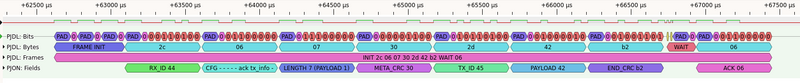
Dataframe Communication Example - two stm32f103c (blue pill) programmed using the library of Pjon available on Platformio.io using arduino framework under the example of Pjon/ARDUINO/Local/SoftwareBitBang/SendAndRecive/device1 and device2.

Device 1 has bus address 44 and Device 2 has bus address 45.
The device 1 send the byte "B" to device 2. The device 2 receive the data, and check for the "B" payload, blink a led and then respond sending a message with the same "B" Payload to device 1. The speed mode used is mode 1
Available modes are:

The protocol is software implemented in the micro controller and the micro controller need to listen actively to be able to catch the communication. In this example the time set for communication listening is 500ms.
Resources
- PJON protocol spec
- PJDL link layer spec
- github project (reference implementation, and documentation) and its PJDL implementation