Error message

  • Warning: count(): Parameter must be an array or an object that implements Countable in theme_table() (line 1998 of /data/sigrok.org/apache/blog/includes/theme.inc).
  • Warning: count(): Parameter must be an array or an object that implements Countable in theme_table() (line 2061 of /data/sigrok.org/apache/blog/includes/theme.inc).
  • Deprecated function: implode(): Passing glue string after array is deprecated. Swap the parameters in drupal_get_feeds() (line 394 of /data/sigrok.org/apache/blog/includes/common.inc).
  • Deprecated function: The each() function is deprecated. This message will be suppressed on further calls in menu_set_active_trail() (line 2405 of /data/sigrok.org/apache/blog/includes/menu.inc).

Joel Holdsworth's blog

sigrok + UNIX = Awesome! - part III - Fun and Games with gpsd

So here I am hanging out at the local hacker space in Richmond. We, the group that meet up every Tuesday evening are small, yet perfectly formed. This evening Paul (MØTZO), a friendly radio ham, and co-founder of our group brought along an interesting device to encode GPS location data in APRS (Automatic Packet Reporting System) packets. These packets are fed into to a VHF radio transmitter which transmits the signal at 144.8 MHz. A network of receivers, run by amateur radio operators receives the packets, and streams them over the internet. An interesting device indeed.

Tonight we were just playing with Paul's GPS board, which contains a U-Blox Neo 6 GPS receiver. As with most GPS receivers, simply powering it on is enough to make it emit coordinates encoded in NMEA 0183 sentences transmitted over UART at 9600bps.

These are trivial to receive with an fx2-based logic analyzer and sigrok-cli:

$ sigrok-cli --driver=fx2lafw --config samplerate=50k \
    --continuous -P uart:baudrate=9600:tx=0 -B uart=tx

With the UART protocol decoder and the ASCII binary output, we can see the NMEA sentences:

Here we can see that we're locked on and receiving coordinates. "cat -v" is used to protect the terminal state from being clobbered by any errant binary data being emitted.

Yawn. Let's make this more interesting.

There is a very interesting package called gpsd. This is a GPS location server than can connect to various types of GPS devices, and can serve the position information over the network. And best of all, thanks to the power of UNIX pipes, we can feed the data from sigrok directly into it:

$ gpsd -N <(sigrok-cli --driver=fx2lafw --config samplerate=50k \
    --continuous -P uart:baudrate=9600:tx=0 -B uart=tx)

There are a variety of gpsd clients available. There's a nice ncurses based client, gpsmon:

And best of all, KDE's Marble integrates with gpsd. Here we see Marble, showing a live stream of location data captured by the fx2lafw firmware, decoded by sigrok, handled by gpsd, plotted by Marble on OpenStreetMap map data - a complete free-software stack! Pretty freetarded:

jhol's sigrok year in review (and 30c3)

Happy New year - 2014! I was barely used to the idea of 2013! - where does the time go?

So I decided it's time for a quick roundup of the year from my own very personal perspective.

Project Status

By any measure, 2013 was a great year for sigrok. The project has grown to over 100kLOC and the number of contributors is growing steadily. Last month was the project's best ever month for contributors - with 12 different people contributing code.

For me it's been particularly heartening to see that many people are interested in contributing. Some have come to provide whole drivers, others providing major features, others contributing all kinds of tweaks and bug fixes. It's great to see the people think that sigrok is a project worth giving their time to. There is even now a commercial fork of sigrok by the DSLogic team.

This year Uwe and Bert continue to be the commit-count-kings building features at all levels of the stack.

In recent months Martin Ling has provided a fresh burst of energy adding the libserialport library and writing drivers for many (all?) Rigol oscilloscopes.

In April we had the first ever PulseView release.

I'm really glad we reached this milestone, because there have been some false starts on the sigrok GUI front. I was keen for the project to get to the point where it was very basically usable. I absolutely did not want to add another tombstone to a graveyard of dead sigrok GUIs. Therefore, v0.1 was not meant to be anything very special, just enough to "close the loop", and provide a basic minimal, not to buggy GUI for sigrok.

Now that this has been achieved, I have been able to add some more exciting features to the project - most notably support for sigrok signal decoding.

PulseView pulseview-0.1.0-195-gdfb9f75 with mixed-signal data, and decoding.

Because of Martin's recent work, there is agreement that we need to make an all-sigrok release as soon as possible. However, PulseView decode support still has some way to go. Therefore, as a compromise I've decided to make decode support a compile-time option in v0.2, which allows fans of the bleeding edge to test this code, but without compromising the overall quality of PulseView in this release.

Once the release is done, I hope decode support will be completed within a short time, and then we can release PulseView v0.3 with the feature enabled.

PulseView is in reasonably good shape, but it's still quite small, and progress is slow. 12 people have contributed to the code in the last year, but I remain by far the largest contributor, contributing 79% of commits in the past 12-months. Some have said that they find the C++ rather impenetrable, but my hope for 2014 is that we broaden out the contributor base so that the project is not so dependent on one person.

It is now easier than ever to contribute to PulseView. I always find GUIs are particularly difficult to design by committee, but once there are some coherent concepts in place, it is much easier for people to understand how their feature should fit into the general scheme of things.

https://events.ccc.de/congress/2013/wiki/Main_Page

30C3

Many of the regular contributors to sigrok, including myself, met at 30c3 in Hamburg for four days of intense sigrok hacking. For me this was my first time to visit the conference, and my first time to meet many of the guys who I've been working alongside for the past two years.

The Sigrok Table at 30C3

We were extremely busy. There's nothing quite like face-to-face meeting to tackle large scale design questions, so much of the time was spent in design meetings trying to bash things out - which to my surprise was quite fruitful, resolving many of the big questions. Whether these ideas ever become code remain to be seen.

Walking round the conference there were a couple of cases where people were using sigrok to solve actual problems. Uwe met a team of guys investigating network controller backdoors, using sigrok to collect SPI data - this without any of us telling them to use the project.

Most of the time was spent working on the code. We hoped to complete the release during the conference. We didn't quite reach this goal - but we are very close. Therefore hopefully there will be a sigrok release within the next couple of weeks.

Finally, I have news that the sigrok project has made the news - specifically Aljazeera TV. The piece is mostly about NSA surveillance, but watch carefully at 0:13 to see a nice sweep of the sigrok table - with some guy, but I don't know who he is.

sigrok + UNIX = Awesome! - part II - Audio

So today I have another example of the powerful ways sigrok-cli can be used, this time with digital audio.

In the modern world there are a wide variety of devices that handle digital audio internally including HiFi equipment and mobile phones. Common signalling schemes include S/PDIF, and various clocked serial PCM schemes. I²S is a specific variant of PCM signalling. It has 3 signals: Clock, Word Select (which signals the beginning of sample words for the left or right channels), and Data which transmits the audio samples MSB first.

sigrok has had support for I²S decoding for a while, and now in the latest Git builds of PulseView, it's possible to see the decode results. This example was taken from the 32-bit I²S example in the sigrok-dumps repository.

But once again thanks to the power of UNIX, sigrok-cli is the far more powerful tool, because it allows us to do interesting things with the decoded information.

The basic syntax for I²S decoding is as follows:

$ sigrok-cli -i 2ch-16bit-16khz.sr -P i2s:sck=0:ws=1:sd=2 -A i2s=right

i2s: "Right channel: f6780000" "Right: f6780000" "R: f6780000" "R"
i2s: "Right channel: f4b80000" "Right: f4b80000" "R: f4b80000" "R"
i2s: "Right channel: f3ac0000" "Right: f3ac0000" "R: f3ac0000" "R"
i2s: "Right channel: f3060000" "Right: f3060000" "R: f3060000" "R"
    ....

Here 32-bit samples are being printed for the right channel only. In itself this is very cool, but we can go much further.

The next step is to extract the data as binary.

sigrok-cli -i 2ch-16bit-16khz.sr -P i2s:sck=0:ws=1:sd=2 -A i2s=right | \
    cut -c22-25 | xxd -r -p > file.bin

The cut command strips all the text except for the 4 most significant hexadecimal nibbles, and in the same way as in the previous blog posting, we use xxd's reverse mode to convert this hexadecimal data to binary.

We now have a binary dump of the PCM data for the channel.

But I want more.

The SoX suite has some really handy tools for manipulating audio, and we can use these tools to convert the audio to a WAV file.

sigrok-cli -i 2ch-16bit-16khz.sr -P i2s:sck=0:ws=1:sd=2 -A i2s=right | \
    cut -c22-25 | xxd -r -p | \
    sox -t raw -B -b 16 -c 1 -e signed-integer -r 16k - right.wav

Here we tell sox that it will receive a raw data stream, containing big endian, 16-bit, signed integer mono audio at 16kHz sample rate, and that it should output the data to a wav file.

Opening the wav file in Audacity, we can see the decoded analog waveform:

...or we can use the sox play tool to play the audio directly out of the headphones:

sigrok-cli -i 2ch-16bit-16khz.sr -P i2s:sck=0:ws=1:sd=2 -A i2s=right | \
    cut -c22-25 | xxd -r -p | \
    play -t raw -B -b 16 -c 1 -e signed-integer -r 16k -

I've never had the chance to try it, but I really want to see if it's possible to do this in real time on a live device.

At this time, it will be a tall order to ask this of libsigrokdecode, but it may nonetheless be possible. It would require a logic analyser capable of continuous streaming, such as the FX2 family of devices, and the I²S logic data would need to be acquired at the lowest possible sample rate without aliasing. If the logic data is captured at a higher sample rate, libsigrokdecode stands no chance of processing all of it.

There is some talk of various ways we can make great increases to libsigrokdecode's performance, so in the future this type of realtime activity should be rather easier to do.

sigrok + UNIX = Awesome!

I've decided it's time to start blogging about the power of sigrok when used together with all the other tools on a typical UNIX machine. This sort of thing usually wouldn't be documented, because it's not really sigrok functionality, but for me these are the most powerful tricks of all.

Here's an example...

Example I - LogicPort BitBanging

Lee Jones has recently started working on a driver for the Intronix LogicPort. The original manufacturer has declined to provide any documentation about the protocol, so Lee has been working hard on reverse engineering it.

The LogicPort internally consists of a Altera EP1C4F324C6 FPGA, with a FTDI FT245BL USB interface.

For USB devices, our typical workflow is to run the vendor software inside a Windows VM and setup a USB passthrough. Then, in the Linux host machine we use usbmon (sometimes via Wireshark) to inspect the packets sent and received. To implement a driver, the developer must then try to replicate this protocol in the driver.

Lee discovered that early in the process of initialising the device, a large block of binary data is sent by the PC to the device. This is a hexadecimal dump of just the beginning part of the packet:

05070507 05070507 05070507 05070507 05070507 05070507 05070507 05070507
04060507 04060507 05070507 04060406 05070507 04060406 04060507 04060507
04060406 05070507 05070406 04060406 04060406 05070507 05070406 04060406
.... 

We suspected that this data is actually being used to cause the FTDI chip to bit-bang an SPI waveform to configure the FPGA. But how can we get more clarity? Answer: with sigrok.

  • First we need to convert this hexadecimal data to binary. xxd has a handy reverse mode that can input hex, and output binary:
    • xxd -r -p dump.txt > dump.bin
  • PulseView has basic support for importing binary data; currently it will assume any file ending in .bin is 8-probe logic data. Opening the file in PulseView, we can see the waveform clearly:
    PulseView now also has very basic support for protocol decoding, which allows us to see the bytes of SPI data.
     
  • Pretty though PulseView decoding is, sigrok-cli is actually more powerful in the end, because with sigrok-cli we can extract the actual bytes from the SPI data stream. Currently sigrok-cli has some problems with its binary input module (these are being addressed in bug #166), so this has to be done in two steps:
    • First, convert the binary data to a sigrok session file:
      • sigrok-cli -I binary:numprobes=2 -i dump.bin -o dump.sr
    • Second, do the decode from the session file:
      • sigrok-cli -i dump.sr -P spi:mosi=0:sck=1
      • Data is decoded:
        • spi: "FF/1FFE"
          spi: "FF/1FFE"
          spi: "5C/1FFE"
          .....
    • Finally we can use some UNIX magic to extract the firmware binary:
      • sigrok-cli -i dump.sr -P spi:mosi=0:sck=1 | cut -c7-8 | xxd -r -p > firmware.bin
      • (One day sigrok-cli will acquire a feature to decode directly into binary, but for now this pipeline works fine)

I think this stuff is really cool. I'm out of time for now, but I'll try and write up some more examples in following posts.

Dogfooding PulseView

After a year of effort, PulseView - sigrok's new logic analyzer, oscilloscope and MSO GUI - is nearly ready for its debut release: v0.1.0.

At this stage we're making a concerted effort to drive up the quality of our release candidate by giving it a thorough round of bug hunting and bug fixing. The range of features offered by PulseView at this stage is quite modest, but those features that it does offer should work well, without crashing or malfunctioning.

In order to experience the joy, or indeed pain, that our users may experience, I've started trying to use PulseView to solve a real problem. This is not the first time I've attempted this task; I've tried to do it several times before, but it hasn't been possible until now to get through this without some kind of crash or error.

The Problem

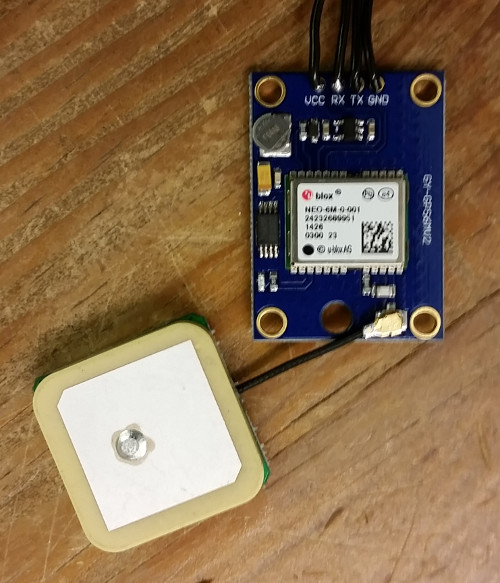
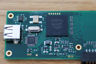
Cypress FX2 based logic analysers have been supported by our fx2lafw open firmware for some time now. Most of these devices are very simple having only a single FX2 on the board. There is a slightly more interesting device: the USBee AX, which has an ADC attached to the upper 8-bits of the FX2's data input. It is therefore a very simple mixed signal device.

I acquired a chinese clone of this device about a year ago: the EE Electronics ESLA201A.

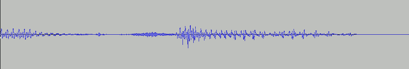
For a while now, I've been working on a branch to add support for these MSO devices both to the fx2lafw firmware and the libsigrok driver. The results so far have been mixed (no pun intended). While the device seems to do a reasonable job of capturing signals from an NE555 board that I have, when I connect the analog input to ground, it goes crazy:

This trace was taken with the analog input grounded, and capturing at 1MHz. Pretty broken.

Yo dawg! I heard you like Logic Analysers...

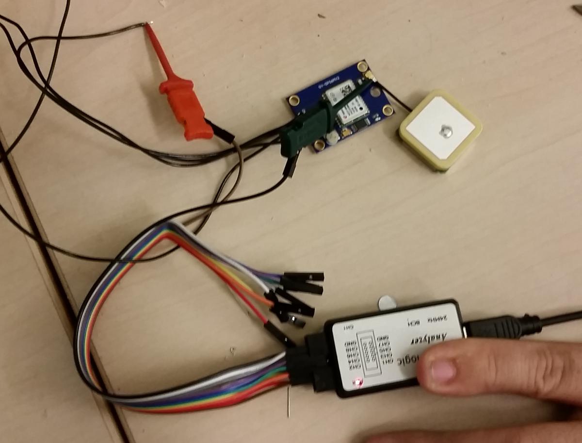
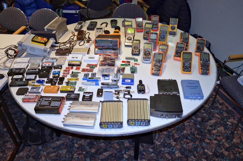
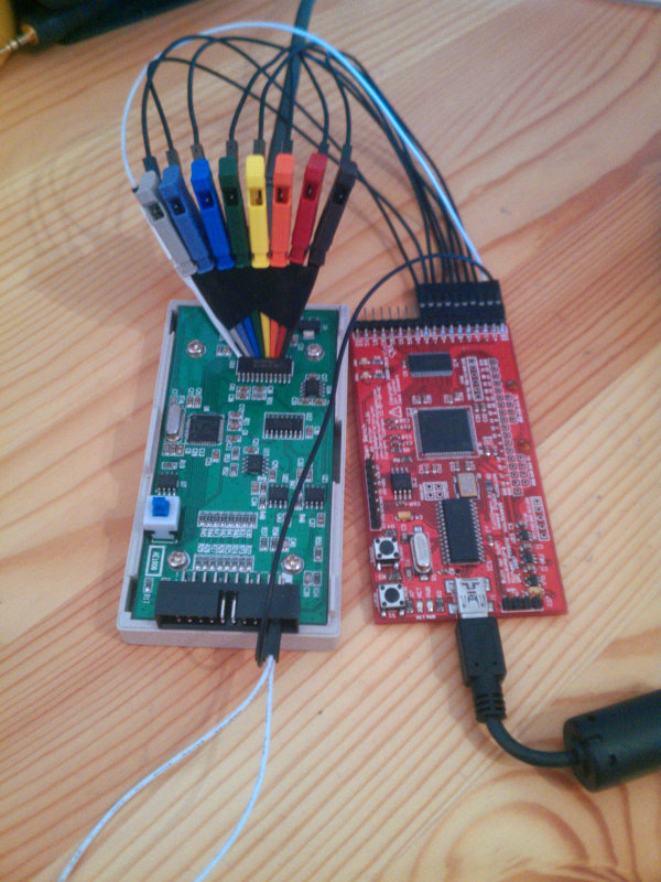
So why is the capture getting corrupted? Fortunately (courtesy of Bert Vermeulen), I have just the tool to find out: The OpenBench Logic Sniffer. This device is a logic analyser capable of sampling at up to 200MHz - fast enough to trace the ESLA201A while it samples.

Here I have attached 8 probes to the 8 data output lines of the ESLA201A's TLC5510I ADC, and a probe to the ADC clock input.

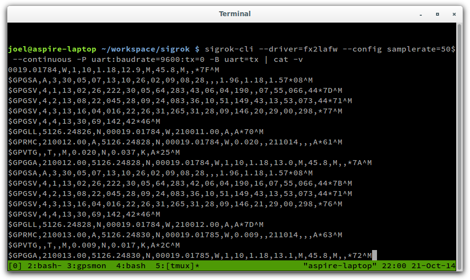
I then set the ESLA201A to sample continuously with sigrok-cli. I like to use cpipe to measure that the pipe throughput is what I would expect it to be, and then dump the data in /dev/null.

$ sigrok-cli --driver=fx2lafw --device samplerate=1M --continuous -O binary | cpipe -vt > /dev/null
thru: 1854.344ms at   69.0kB/s (  69.0kB/s avg)  128.0kB
thru: 132.646ms at  965.0kB/s ( 128.8kB/s avg)  256.0kB
thru: 127.458ms at 1004.3kB/s ( 181.6kB/s avg)  384.0kB
thru: 132.681ms at  964.7kB/s ( 227.8kB/s avg)  512.0kB
thru: 127.580ms at 1003.3kB/s ( 269.5kB/s avg)  640.0kB
thru: 132.563ms at  965.6kB/s ( 306.3kB/s avg)  768.0kB
thru: 132.689ms at  964.7kB/s ( 339.4kB/s avg)  896.0kB

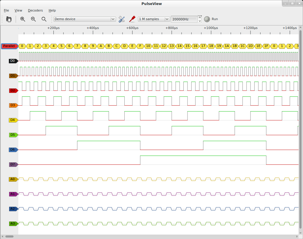
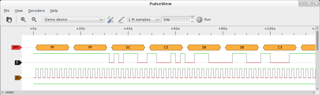
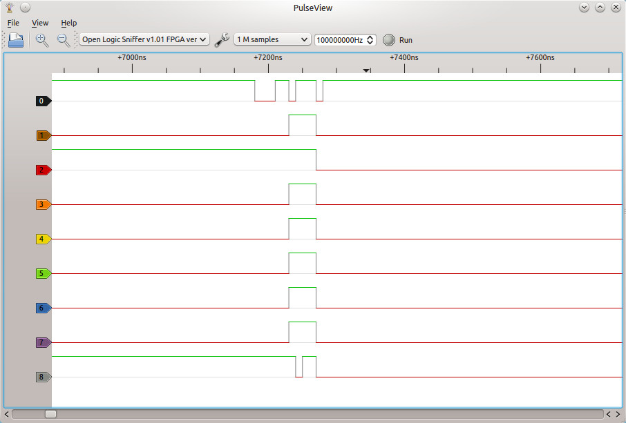
...then I set PulseView to capture a trace:

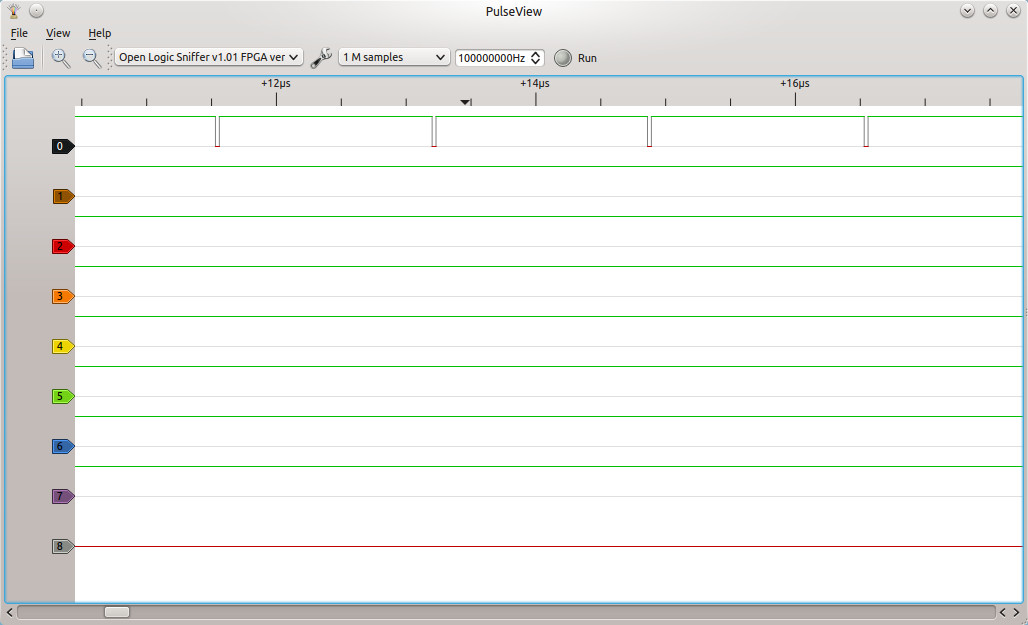
So far this is what I would expect to see. Channel 0 is the clock input, and channels 1-8 are the data output, where channel 8 is the MSB. Therefore the ADC is reading a value of 127, which for a 0V input is correct.

So could this be an issue of timing? The TLC5510I has a minimum high and low clock pulse duration of 25ns. To find out, we will use PulseView's cursors feature.

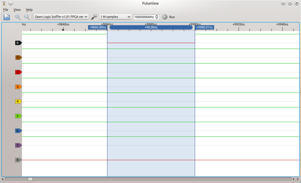
Putting the cursors around the trough, we can measure a low-duration of 40ns. So no problem there. There are no other constraints on the timing signal - they don't have to be symmetrical pulses.

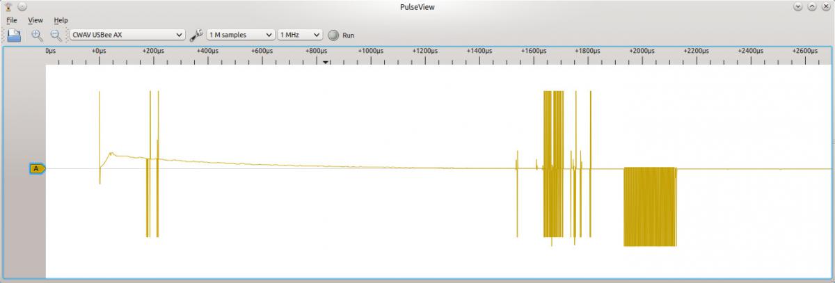
So I kept repeatedly clicking Run to see if things would always run so smoothly. Suddenly this happened...
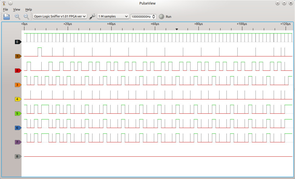
Lulwat?

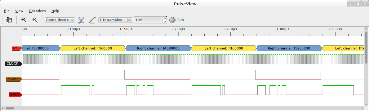
The ADC seems to be having some kind of spaz-attack. So far I haven't been able to figure out exactly what has caused this. However, there do occasionally seem to be problems with the clock signal:

If this logic analyser is seeing what the ADC is seeing, this would explain a lot about why the ADC has gone crazy. The question to determine whether this is a problem with the fx2lafw firmware, or whether there is some signal integrity problem - and what would cause that.

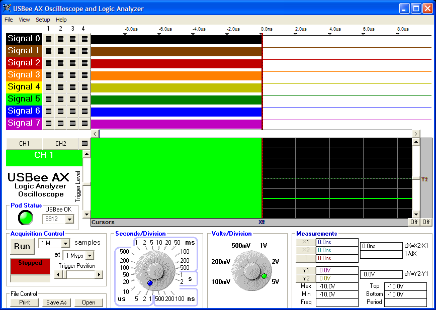
By way of comparison, I decided to see how the USBee software suite would fair on the same problem. So I fired up my trusty Windows XP VM. Interestingly, it too exhibited a very similar behaviour.

I hadn't done any logic analysis with the official firmware before, so I wasn't sure if it would show some mistake I had made in the shape of my clock pulse. In the end it showed a clock signal that was almost identical - except the low-pulses were 30ns rather than 40ns.

Conclusion

I suspect even if I figure out the cause of the corruption, the device will never be a very good oscilloscope, if it has these kinds of ground bounce effects. This is the decay you can see in the analog trace above, and if there are issues with the design either on the digital or analog side, there may not be much I can do about them.

Having said that, even if the board does have digital signalling issues, attaching lots of logic analyser wires to it will make them much worse, so some of the issues we are observing here may have been self induced.

Any suggestions would be welcome.

But anyway, this is all beside the point. PulseView managed to come through this experiment without crashing and delivered some interesting insights.

Subscribe to RSS - Joel Holdsworth's blog