Difference between revisions of "Victor 70C"
| Line 79: | Line 79: | ||
| 0 | | 0 | ||
| | | | ||
| Unused (always contains 0x50) | | ''Unused (always contains 0x50)'' | ||
|- | |- | ||
| 1 | | 1 | ||
| | | | ||
| Unused (always contains 0xb0) | | ''Unused (always contains 0xb0)'' | ||
|- | |- | ||
| 2 | | 2 | ||
| | | | ||
| Flags | | ''Flags'' | ||
|- | |- | ||
| Line 104: | Line 104: | ||
| 3 | | 3 | ||
| | | | ||
| Major measurement modes | | ''Major measurement modes'' | ||
|- | |- | ||
| | | | ||
| Line 141: | Line 141: | ||
| 4 | | 4 | ||
| | | | ||
| Value factors and extra measurement modes | | ''Value factors and extra measurement modes'' | ||
|- | |- | ||
| | | | ||
| Line 178: | Line 178: | ||
| 5 | | 5 | ||
| | | | ||
| Extra flags and value factors | | ''Extra flags and value factors'' | ||
|- | |- | ||
| | | | ||
| Line 216: | Line 216: | ||
| 6 | | 6 | ||
| | | | ||
| Flags | | ''Flags'' | ||
|- | |- | ||
| | | | ||
| Line 253: | Line 253: | ||
| 7 | | 7 | ||
| | | | ||
| Decimal point position | | ''Decimal point position'' | ||
|- | |||
| | |||
| 0 | |||
| No decimal point | |||
|- | |||
| | |||
| 1 | |||
| Rightmost (1 digit after point) | |||
|- | |||
| | |||
| 2 | |||
| Middle (2 digits after point) | |||
|- | |||
| | |||
| 3 | |||
| Leftmost (3 digits after point) | |||
|- | |||
| | |||
| 4 | |||
| unused. | |||
|- | |||
| | |||
| 5 | |||
| unused. | |||
|- | |||
| | |||
| 6 | |||
| unused. | |||
|- | |||
| | |||
| 7 | |||
| unused. | |||
|- | |- | ||
| 8 | | 8 | ||
| | | | ||
| Unused (always contains 0x04) | | ''Unused (always contains 0x04)'' | ||
|- | |- | ||
| 9 | | 9 | ||
| | | | ||
| | | Least significant digit on display. | ||
|- | |- | ||
| 10 | | 10 | ||
| | | | ||
| | | Second digit from right. | ||
|- | |- | ||
| 11 | | 11 | ||
| | | | ||
| | | Second digit from left. | ||
|- | |- | ||
| 12 | | 12 | ||
| | | | ||
| | | Most significant digit. | ||
|- | |- | ||
Revision as of 14:21, 18 August 2012

The Victor 70C is a 4000 counts, CAT II handheld digital multimeter with USB connectivity. It is also sold as the EZA EZ-735
See Victor 70C/Info for more details (such as lsusb -vvv output) about the device.
Hardware
- Fortune Semiconductor FS9922-DMM4 multimeter chip
- NXP HEF4066BT quadruple bilateral switches
- Microchip TC7660E charge pump DC-to-DC voltage converter
- Texas Instruments 27L2C precision dual op-amp
- Unknown USB interface chip (HID)
Photos
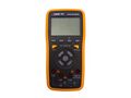
Device, front
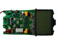
PCB, front
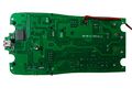
PCB, bottom
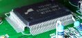
DMM/LCD chip
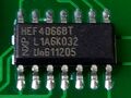
NXP HEF4066BT
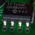
Microchip TC7660E
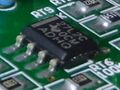
TI 27L2C
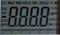
LCD


Protocol
The device registers on the USB host as a HID-class device. The protocol payload is 14 bytes of data which can be read from endpoint 1, at no more than 1 Hz.
The 14-byte chunk is somewhat obfuscated. To deobfuscate, subtract the ASCII value of the following string from each of the 14 bytes in turn: jodenxunickxia. Then reshuffle the bytes into different positions, according to the following table:
| Original position | 0 | 1 | 2 | 3 | 4 | 5 | 6 | 7 | 8 | 9 | 10 | 11 | 12 | 13 |
| Final position | 6 | 13 | 5 | 11 | 2 | 7 | 9 | 8 | 3 | 10 | 12 | 0 | 4 | 1 |
The deobfuscated payload is then structured as follows:
| Byte | Bit | Value |
|---|---|---|
| 0 | Unused (always contains 0x50) | |
| 1 | Unused (always contains 0xb0) | |
| 2 | Flags | |
| 0 | Minus | |
| 1-7 | Unused. | |
| 3 | Major measurement modes | |
| 0 | Voltage measurement mode, combined with AC or DC flags in byte 6. In combination with the Diode flag in byte 4, signifies diode testing mode. | |
| 1 | Current measurement mode, combined with AC or DC flags in byte 6. | |
| 2 | Resistance measurement mode. In combination with the Continuity flag in byte 4, signifies continuity testing mode. | |
| 3 | Unused. | |
| 4 | Frequency measurement mode. | |
| 5 | Capacitance measurement mode. | |
| 6 | Temperate measurement mode, in Celcius. | |
| 7 | Temperature measurement mode, in Fahrenheit. | |
| 4 | Value factors and extra measurement modes | |
| 0 | µ (Micro) | |
| 1 | m (Milli) | |
| 2 | k (Kilo) | |
| 3 | M (Mega) | |
| 4 | Continuity (in combination with resistance mode in byte 3) | |
| 5 | Diode (in combination with voltage mode in byte 3) | |
| 6 | Duty cycle measurement mode. | |
| 7 | unused. | |
| 5 | Extra flags and value factors | |
| 0 | unused. | |
| 1 | unused. | |
| 2 | Max measurement mode. | |
| 3 | Min measurement mode. | |
| 4 | unused. | |
| 5 | unused. | |
| 6 | n (Nano) | |
| 7 | unused.
| |
| 6 | Flags | |
| 0 | unused. | |
| 1 | unused. | |
| 2 | Auto-ranging mode. | |
| 3 | DC measurement. | |
| 4 | AC measurement. | |
| 5 | Relative measurement. | |
| 6 | Hold mode. | |
| 7 | unused. | |
| 7 | Decimal point position | |
| 0 | No decimal point | |
| 1 | Rightmost (1 digit after point) | |
| 2 | Middle (2 digits after point) | |
| 3 | Leftmost (3 digits after point) | |
| 4 | unused. | |
| 5 | unused. | |
| 6 | unused. | |
| 7 | unused. | |
| 8 | Unused (always contains 0x04) | |
| 9 | Least significant digit on display. | |
| 10 | Second digit from right. | |
| 11 | Second digit from left. | |
| 12 | Most significant digit. | |
| 13 | Unused (always contains 0xd4) |
Resources
- RoastLogger: Input Devices (Victor Victor 86B/86C support)
- Dave Ansell Science Communication: Victor 86C multimeter USB encoding for linux (PHP)
- victor86b-usb-interface: USB interface for Victor 86B Digital Multimeter using HIDAPI (see also here)
- Sparkfun: Victor 70C (manual, software)
- Github: victor70c (HIDAPI)
- Random review / photos