Difference between revisions of "SainSmart DDS140"
Jump to navigation
Jump to search
SamantazFox (talk | contribs) (Add pictures for the signal generator extension module) |
SamantazFox (talk | contribs) |
||
| Line 52: | Line 52: | ||
File:Saintsmart dds140 - signal generator - PCB bottom.jpg|<small>PCB, bottom</small> | File:Saintsmart dds140 - signal generator - PCB bottom.jpg|<small>PCB, bottom</small> | ||
File:Saintsmart dds140 - signal generator - PCB top (closeup).jpg|<small>PCB, top (closer view)</small> | File:Saintsmart dds140 - signal generator - PCB top (closeup).jpg|<small>PCB, top (closer view)</small> | ||
</gallery> | |||
== Photos - Logic analyzer extension == | |||
<gallery> | |||
File:Saintsmart dds140 - logic analyzer - device top.jpg|<small>Device, top</small> | |||
File:Saintsmart dds140 - logic analyzer - PCB top.jpg|<small>PCB, top</small> | |||
File:Saintsmart dds140 - logic analyzer - PCB top (closeup).jpg|<small>PCB, top (closer view)</small> | |||
</gallery> | </gallery> | ||
Revision as of 23:18, 15 February 2020

The SainSmart DDS140 is a USB-based, 2-channel oscilloscope with an analog bandwidth of 40MS/s and 200MS/s sampling rate.
Optionally, it also supports usage as signal generator or logic analyzer.
See SainSmart DDS140/Info for more details (such as lsusb -v output) about the device.
Hardware
- USB: Cypress CY7C68013A-100AXC (FX2LP) (datasheet)
- 64-kbyte I²C EEPROM: Microchip 24LC64I (datasheet)
- Dual 8bit, 100MSPS ADC: MXTronix MXT2088 (datasheet)
- 5x CMOS differential 4-channel analog mux/demux with logic-level conversion: Texas Instruments CD4052BM (datasheet)
- CPLD: Altera MAX II EPM240T100CN (datasheet)
- 64K x 16 CMOS anyc SRAM (8ns): ISSI IS61LV6416-8TI (datasheet)
- Dual voltage comparator: TI LM393 (datasheet)
- 1A low-dropout voltage regulator (3.3V): Advanced Monolithic Systems AMS1117-3.3 (datasheet)
- Crystal: 24MHz (for Cypres FX2)
- Crystal: 80MHz (for Altera MAX II)
Photos - Oscillocope (main unit)
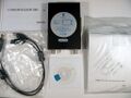
Package contents
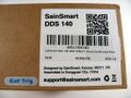
Sticker
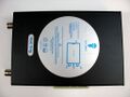
Device, top
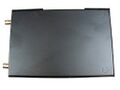
Device, bottom
USB
Connectors
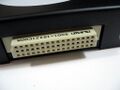
2nd connector
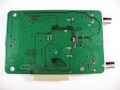
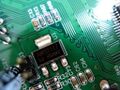
PCB, top
PCB, bottom
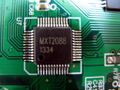
MXT2088
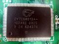
Cypress FX2
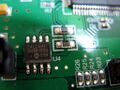
Microchip 24LC64I
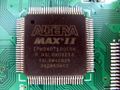
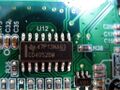
Altera MAXII EPM240T100CN
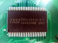
ISSI IS61LV6416-8TI
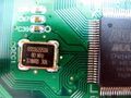
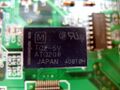
80MHz crystal
AMS1117-3.3
TI CD4502BM
LM393
?
?


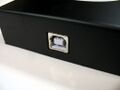
Photos - Signal generator extension
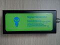
Device, top
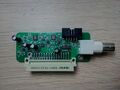
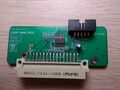
PCB, top
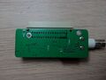
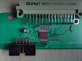
PCB, bottom
PCB, top (closer view)


.jpg)
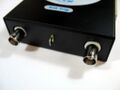
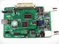
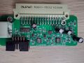
Photos - Logic analyzer extension

Device, top
PCB, top
PCB, top (closer view)


.jpg)